The arc flash boundary is the distance from energized electrical equipment at which the incident energy released by an arc flash would fall to 1.2 calories per square centimeter (cal/cm²), the level at which bare skin receives a second-degree burn. That is the definition OSHA uses in its fact sheet on establishing boundaries around arc flash hazards. The distance is calculated for one specific piece of gear and stated explicitly in the arc flash study an engineer performs on that gear, then printed on its label. Anyone crossing that distance while the equipment is energized and open needs arc-rated protective clothing.
Picture a maintenance supervisor at a wastewater plant with a work order to tighten a lug, the bolted connection where a feeder cable lands on a breaker, that an infrared scan of the panel flagged as running hot last month. The label on the switchboard door gives her an incident energy figure at a stated working distance and an arc flash boundary in feet and inches. Those two numbers came out of a completed study of that switchboard. They do not transfer to the motor control center twenty feet down the same wall, and they will change if anything upstream of that switchboard changes.
That last point carries the whole idea. The boundary is a measured output of an engineering model, and it belongs to one bus at one moment in the life of your electrical system.
What does the arc flash boundary actually measure?
It measures heat. Specifically, it measures incident energy, the thermal energy that lands on a surface a given distance from an arc, expressed in cal/cm². The three inputs that move that number are available fault current (how much current the system can push into the fault), clearing time (how long the upstream protective device lets the arc burn), and distance. OSHA states plainly that arc flash danger depends mainly on amperage, cycle time, and worker distance. System voltage sits further down that list.
That surprises people. OSHA notes on the same page that arc temperatures can exceed 35,000 degrees Fahrenheit, roughly four times as hot as the surface of the sun, and warns that low-voltage systems such as 120/208V can still produce arcs energetic enough to burn skin, ignite clothing, and kill. A 208V panel in a school kitchen is not automatically a low-hazard panel. Its hazard depends on what the utility transformer can deliver into a fault there and how fast something upstream opens.
What are the three boundaries for arc flash?
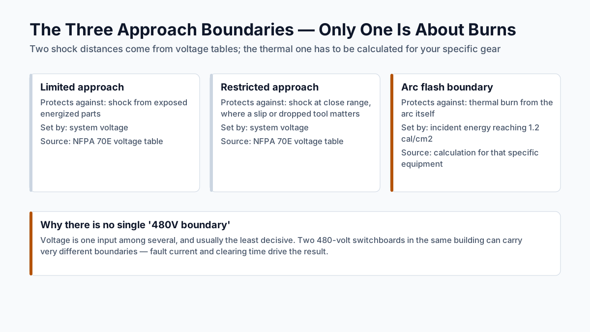
There are three approach boundaries, and only one of them is about burns. The limited approach boundary and the restricted approach boundary are shock-protection distances set by system voltage, read off the AC and DC voltage tables in NFPA 70E, the National Fire Protection Association's standard for electrical safety in the workplace. The arc flash boundary is a thermal distance set by calculation. OSHA's fact sheet makes the point that the arc flash boundary has no fixed relationship to the two shock boundaries: it can land inside them or well outside them.
| Boundary | What sets the distance | What it protects against | Where the number comes from |
|---|---|---|---|
| Limited approach | System voltage | Shock from contact with exposed energized parts | NFPA 70E voltage table |
| Restricted approach | System voltage | Shock at close range, where a slip or a dropped tool matters | NFPA 70E voltage table |
| Arc flash boundary | Incident energy reaching 1.2 cal/cm² | Thermal burn from the arc itself | Calculation for that specific equipment |
Here is how that plays out on real gear. A 480-volt switchboard fed by a large service transformer, protected by a device that takes a few tenths of a second to open, can have a modest shock boundary and an arc flash boundary that reaches out past where a technician would stand to operate it. A 15kV switch can have a large shock boundary and a small arc flash boundary, because a fast relay clears the fault before much energy is released. Reading one boundary off the other is guesswork.
How do you determine the arc flash boundary?
You model the system, then solve for distance. The industry method is IEEE 1584-2018, the IEEE Guide for Performing Arc-Flash Hazard Calculations, which supplies the equations for arcing current, incident energy, and the arc flash boundary distance. Its published scope covers three-phase AC systems from 208V to 15kV. It does not cover single-phase AC or DC systems, and it does not include guidance on selecting protective clothing.
Getting to those equations means field work, and most of it lands on you before an engineer opens a spreadsheet. You need a one-line diagram, the single-page map showing how power flows from the utility service through each transformer, breaker, and bus in your building. A bus is the common set of conductors that all the breakers in a given piece of gear connect to, and it is the level at which incident energy gets calculated, so every bus in the model needs its own set of data. You need the available fault current at your service, which the utility publishes on request. You need nameplate data from transformers, conductor lengths and sizes, and the settings on your protective devices, including where the dials on each trip unit sit today. The trip unit is the electronic module inside a modern breaker that decides how much current it tolerates and for how long before it opens.
If you do not have a current one-line diagram, you are in ordinary company, and building one is part of the work. Field data collection is also the part of an arc flash program facility managers dread, because it means opening gear and, on some buses, taking an outage. Arc Flash Florida schedules that walk-down against existing maintenance windows and handles the drawing, the engineering, the labels, and the training in one pass, which is the practical answer to the disruption question.
Once the model exists, the software calculates arcing current at each bus, reads the clearing time off the protective device curve for that current, computes incident energy at the working distance, and then solves for the distance at which incident energy equals 1.2 cal/cm². That distance is your arc flash boundary for that bus. Choosing what a worker wears inside it is a separate step, governed by NFPA 70E. IEEE 1584 also stays out of overcurrent coordination, the separate exercise of setting protective devices so the one closest to a fault trips first while the ones upstream hold, though coordination and arc flash results are tightly linked in practice.
Section 130.5 of NFPA 70E is where the arc flash risk assessment lives, including determining the boundary and choosing between two permitted methods: an incident energy analysis, and the PPE category table method. The table method is a legitimate path and a lighter lift. It gets you to a PPE category using equipment type and the applicability conditions the standard sets for its use, without a full model of your system. What it does not give you is a calculated incident energy value or a boundary distance derived from your own fault current and clearing times, which is what insurers, corporate safety programs, and the electrician standing in front of the gear are looking for.
What is the boundary for 480V equipment?
There is no single number, and any source that hands you one for 480 volts is describing an example system of its own. Voltage is one input among several, and it is usually the least decisive. 480Y/277V distribution feeds lighting and motor loads across commercial and industrial buildings, so it is the equipment class this question usually comes up about, and two 480-volt switchboards in the same building can carry very different boundaries.
Consider a hospital campus with two switchboards on the same service. One is protected upstream by a breaker with a fast instantaneous trip that opens in a few cycles. The arc burns briefly, the energy delivered is small, and the boundary sits close to the enclosure. The second board sits downstream of a device that was deliberately delayed so it would coordinate with the breakers below it, holding for several tenths of a second before it opens. Same voltage, same building, same utility. The longer the arc burns, the more energy lands on whoever is standing there, and that second boundary can extend across the aisle. Clearing time, not voltage, is the number that moves the answer most.
This is also why arc flash boundaries sometimes shrink after a study. If an engineer can safely speed up an upstream device, or add a maintenance switch that temporarily lowers the trip threshold during energized work, the calculated energy drops and the boundary comes in with it. That kind of finding is one of the more useful things a study produces.
Is it safe to stand just outside the arc flash boundary?
No. The 1.2 cal/cm² threshold marks where unprotected skin begins to suffer a second-degree burn, so a person standing exactly at the boundary is at the edge of injury. Jim Phillips, P.E., who serves as vice-chair of the IEEE 1584 arc flash working group and sits on the NFPA 70E technical committee, puts it directly: "The arc-flash boundary is a planning tool, not a permission slip."
Phillips also points out that the calculation addresses thermal energy and leaves the rest of the event out of the picture. An arcing fault throws molten metal and hardware fragments, produces a pressure wave that can knock a person down or blow a door open, emits light intense enough to injure eyes, and generates a sound level that can damage hearing. None of those stop at a calculated line. His standing advice for anyone near open, energized equipment is short: "If you're not wearing properly rated arc-flash PPE, leave the area."
So treat the boundary as what it is, an input to your work planning. It tells you where to set barricades, who needs to be in arc-rated gear, and when a job is worth the trouble of scheduling an outage instead. That is the value a study delivers: a hazard nobody can see, converted into a distance you can measure with a tape and a protection level you can buy.
What does OSHA require for arc flash boundaries?
For most general-industry facilities, OSHA has no dedicated rule that names a boundary distance. It enforces arc flash protection through the General Duty Clause, Section 5(a)(1) of the OSH Act, which requires each employer to furnish a workplace "free from recognized hazards that are causing or are likely to cause death or serious physical harm," and it points to NFPA 70E as the recognized consensus practice for meeting that duty. NFPA 70E carries the weight of a consensus standard that OSHA cites, so enforcement usually shows up after an incident, a complaint, an insurance audit, or a corporate safety review.
One number gets misapplied here often, and it produces a real gap in written safety programs. Under OSHA's utility-specific standard, 29 CFR 1910.269(l)(8)(v) and its Appendix E, arc-rated protection is not required for calculated exposures of 2 cal/cm² or less, and OSHA cites 1.2 to 1.5 cal/cm² in that appendix as the burn-injury threshold. That 2 cal/cm² allowance applies to electric power generation, transmission, and distribution work. If you run a food plant, a hospital, or a data center, that provision is not your rule, and importing it into your electrical safety program puts a gap between what your program says and what a consensus standard expects.
What makes a boundary distance go out of date?
The label is true for the system that was modeled. Change an input and the output moves, whether or not anyone reprints the sticker. Adding a standby generator after a close call in hurricane season, which is how a lot of Florida plants and hospital wings end up with one, gives you a second source with its own fault current and its own clearing behavior whenever the transfer switch is on generator. Upgrading a service or adding a second one raises available fault current across the gear it feeds. Replacing a breaker with a different frame or a different trip unit changes clearing time. So does an electrician quietly turning up a trip dial to stop a nuisance trip on a chiller, which is a five-second act that can push a boundary distance well past where it sat the day the label was printed.
The utility can move your numbers without telling you. A transformer swap for a larger unit on a growing campus raises the fault current at your service, and the study on your shelf still shows yesterday's figure.
There is a quieter failure mode too, and it shows up hard in electrical rooms near the water. Every incident energy calculation assumes the upstream protective device opens in the time its curve promises. A breaker in a coastal plant room that has never been exercised, with salt air working on its mechanism and contacts for a decade, may take longer than the curve says or fail to open at all. That is a maintenance question, and no recalculation fixes it. It is one reason a study, a maintenance plan, and a training program tend to arrive as one conversation.
If you want to know your actual boundary numbers, start with three things you can check this week: whether your one-line diagram matches what is currently installed, whether anyone has requested available fault current from your utility recently, and what the labels on your gear say today. Labels that are missing, generic, or older than your last electrical project are the gap. Closing it is a planned pass through your facility, and it ends with a number on every door that a technician can act on.
Frequently asked questions
What is the arc flash boundary?
The arc flash boundary is the distance from energized electrical equipment at which the incident energy from an arc flash would fall to 1.2 calories per square centimeter (cal/cm2), the level that causes a second-degree burn on bare skin. It is calculated for one specific piece of equipment and printed on that equipment's label. Anyone inside it while the gear is energized and open needs arc-rated protective clothing.
What are the three boundaries for arc flash?
The limited approach boundary and the restricted approach boundary are shock-protection distances set by system voltage, using the AC and DC voltage tables in NFPA 70E. The arc flash boundary is a thermal distance set by incident energy calculation. OSHA states the arc flash boundary has no fixed relationship to the two shock boundaries and can fall inside or outside them.
What is the arc flash boundary for 480V?
There is no single 480V figure. Two 480-volt switchboards in the same building can have very different boundaries, because incident energy is driven mainly by available fault current and how long the upstream protective device takes to clear the arc. Only an incident energy analysis of your specific equipment produces a valid distance.
How do you determine the arc flash boundary?
An engineer models your system using IEEE 1584-2018, the IEEE Guide for Performing Arc-Flash Hazard Calculations, which covers three-phase AC systems from 208V to 15kV. The model needs a current one-line diagram, the utility's available fault current, transformer and conductor data, and the actual protective device settings. The software calculates arcing current and incident energy at each bus, then solves for the distance at which incident energy equals 1.2 cal/cm2.
Sources reviewed
- OSHA -- Establishing Boundaries Around Arc Flash Hazards (fact sheet, updated Nov 2024) Defines the three approach boundaries (restricted, limited, arc flash) and states the arc flash boundary is independent of the shock-protection boundaries, capable of falling inside or outside them.
- OSHA -- 29 CFR 1910.269 Appendix E Paragraph (l)(8)(v) of 1910.269 does not require arc-rated protection for exposures of 2 cal/cm2 or less; cites the 1.2-1.5 cal/cm2 range as the burn-injury threshold.
- OSHA -- OSH Act Section 5, Duties (General Duty Clause) Exact statutory text of the General Duty Clause, Section 5(a)(1), requiring a workplace free from recognized hazards likely to cause death or serious physical harm.
- OSHA -- Electrical, Electric-Arc Flash Hazards Arc temperatures can exceed 35,000 degrees F; arc flash danger depends mainly on amperage, cycle time, and distance, not voltage; low-voltage (120/208V) systems can still cause fatal arc flash injury; references NFPA 70E and 29 CFR 1910.333.
- IEEE SA -- 1584-2018, IEEE Guide for Performing Arc-Flash Hazard Calculations Official scope of IEEE 1584-2018: provides models to determine arc-flash hazard distance (arc flash boundary) and incident energy; applies to 3-phase AC systems 208V-15kV; excludes single-phase AC, DC, and PPE recommendations.
- NFPA -- NFPA 70E, Standard for Electrical Safety in the Workplace (product page) Official NFPA page for the NFPA 70E standard -- use only to confirm the standard's title/publisher; full section-level text could not be fetched/verified in this pass (JS-rendered viewer), so no specific 130.5 subsection letter should be asserted from it.
- Brainfiller (Jim Phillips, P.E.) -- 'Is the Arc Flash Boundary a Safe Distance?' Source of the attributed expert quotes on the arc flash boundary being a planning tool, not a permission slip, and on residual hazards (debris, pressure wave, light, sound) just outside the boundary.
- Arc Flash Florida -- Arc Flash Hazard Analysis and Risk Assessment (client's own site) First-party description of what the client's own arc flash hazard analysis service determines (incident energy, arc flash boundaries, required PPE) -- for context/differentiation check only, not a citation to insert as an outbound authority.